
Components of Galvanometer Optical Scanner
Galvanometer Optical Scanner
|
Galvanometer Optical Scanner is the motor with high precision position sensor which detects position to adjust the scan angle of the mirror reflecting laser beam. It has a variety of applications in combination with laser beam, such as laser marker, microscopes, and LiDAR. |
Overall Structure
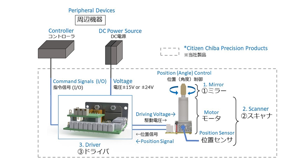
Galvanometer Optical Scanner is structured by following three (3) parts:
- Mirror ‥‥ Reflects the laser beam
- Scanner ‥‥ Drives the mirror
- Driver ‥‥ Controls the position of scanner
The mirror size would be selected according to the diameter of laser spot reflected by the mirror and then the driver would be selected after scanner is selected according to the mirror size. The perfect specification would be found automatically once diameter of laser spot is selected.
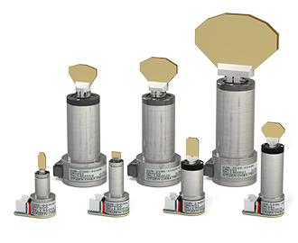
Mirror
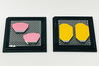
Mirror is the part which is mounted on the shaft of the scanner and reflects the laser beam.
It has a variety of sizes and coatings according to the type of laser beam.
The mirror size depends on the diameter of reflecting laser spot. However, larger the mirror, harder to operate in high speed due to increase of inertia.
Scanner
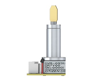
Scanner is the device which controls the scanning position (or angle) of the mirror.
It has a sensor to detect the present position. The size of scanner depends on the size of the mirror or how a customer would like to drive the mirror. For example, if a customer would like to use a large mirror, the scanner must be large in size also.
Driver
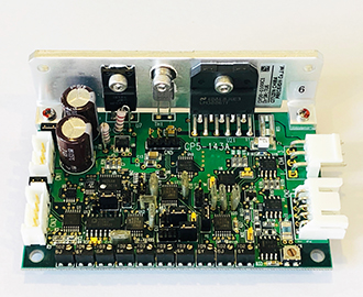
Driver is the device which supplies electric power to drive the scanner.
It succeeded to implement high speed and high precision position control by calculation based on the position signal, motor current, and command signal from the controller.
Peripheral Devices
The following two (2) items are also required to operate a galvanometer optical scanner:
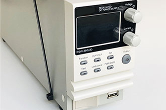
- Power Source ‥‥ Supplies the power (±15V or ±24V)to the driver
- Controller ‥‥ Commands the position of scanner to the driver (output the position command signal) / Servo ON/OFF
