Scanner for Galvanometer Optical Scanner
Scanner for Galvanometer Optical Scanner
|
A scanner of Galvanometer Optical Scanner is a drive source which drives a mirror and consists oscillating motor and position detector. The factors that should be considered in particular when selecting a galvanometer scanner are: (1) scanner size and (2) scan angle. The scanner size is selected by the mirror size, and the scan angle is selected by the optical system design. We, Citizen Chiba Precision, use an optical analog sensor as the position detector. The feature of the motor for galvanometer scanner is it uses a motor specialized for rotating in a limited angle. By structurally limiting the rotation angle, there is an advantages such as: (1) The commutator and brush required for DC motors and the magnetic pole sensor for commutation required for brushless motors, are not required. (2) It reduces friction factors of the motor. (3) The coreless motor structure enables highly responsive and highly accurate angle control. The galvanometer scanner is required to move to the target angle at high speed. Therefore, as it is clear by the equation of motion stated in the rotary motion system: Rotation Torque [N・m] = Inertia [kg・m2] ✕ Angular Accelerationα [rad/sec2] , it is important to generate high torque instantaneously and to have a small rotor inertia in order to obtain rapid acceleration. 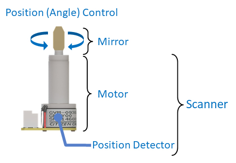 |
Scanner Sizes
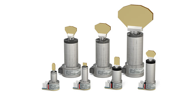
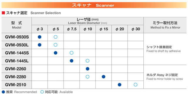
As we mentioned earlier, the scanner size is selected by the mirror size. All of our scanners are optimally designed according to the mirror size. Our model numbers, such as GVM-0930 and GVM-1445 for example, have 4 digits numbers and first two digits indicate the diameter of the scanner.
It is important to use by the optimal combination of mirror size and scanner size.
Scan Angle
Our galvanometer scanner can drive in the scan angle up to ±10° to ±20°(mechanical angle) as standard. Linearity, which affects accuracy, tends to deteriorate above ±10°.
We can set the maximum scan angle to less than ±10° according to the specifications. Please ask our sales representatives or authorized distributors for more details.
Cable Length
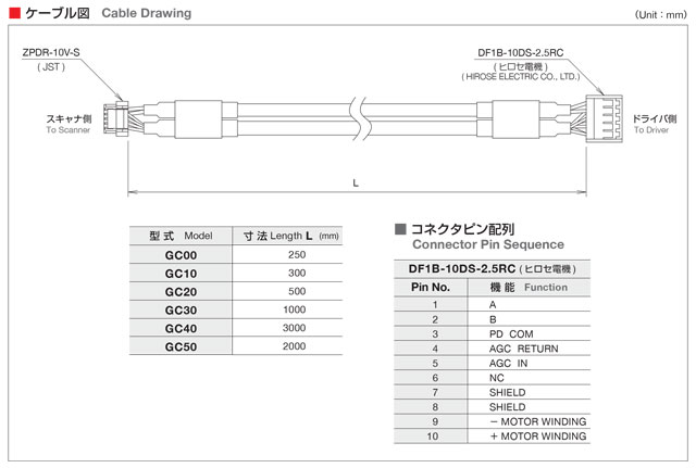
The length of the connection cable between the scanner and the driver is also included in the model number. Large scanners, larger than GVM-2260, have a direct cable connection. Small scanners, smaller than GVM-1445, use a dedicated extension cable (GCxx) to connect with the connector.
The cable length affects the electrical resistance and inductance of the scanner, and relates to the operating speed of the scanner. In general, a short cable has lower electrical resistance and small inductance which is advantageous for operation. However, our standard products has almost no effect on performance even with maximum three (3) meters long cable.
Since the cable transmits the analog position signal output from the scanner sensor, we use a a noise-proof cable.
Shape of the Output Shaft
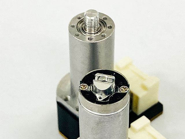
The shape of the mirror holder differs according to the scanner size. For scanners larger than GVM-2260, we fix a holder with a mirror on the output shaft. You can remove the mirror simply by loosening the screw.
For scanners smaller than GVM-1445, the mirror holder is glued directly to the output shaft. Therefore, the mirror cannot be removed to replace but the inertia can be kept small, which is advantageous for operation. Because such a small inertia differences can be a significant effect, this shape is our standard for the small scanners.
It is possible to glue the mirror provided by the customer. Please feel free to ask our sales representatives or authorized distributors.
Mirror Angle Against Cable Outlet and With/Without Mirror
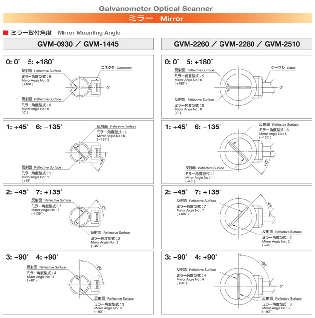
The cable outlet and mirror position can be selected based on the structure around the galvanometer scanner and its posture.
Position Detector
Our position detector uses patented optical analog sensor. We are sorry that we do not have a digital galvanometer scanner (digital galvo) equipped with an encoder at this moment.
The analog position detector (optical) detects the angular position by emitting laser beam on the reflector attached to the shaft end and it converts the reflected laser beam to voltage by the light receiving element. Our position detector is light in weight and suitable for high-speed operation because it only requires to attach reflector to the moving part.
Since there are individual differences in LED (the light source) and photodiode (the light receiving element), it is necessary to adjust the driver for each galvanometer scanner. And also, in order to reduce the drift by the temperature characteristics of LED and the photodiode, the correction circuit is incorporated in the driver. So, we deliver by pairing the adjusted driver and the scanner together in link.
The digital position detector attaches a rotary encoder to the end of the shaft and it outputs angle information by digital signal. High positioning accuracy can be expected by using a high resolution encoder. The advantage for high position accuracy is that the encoder is less susceptible to temperature changes and noise. However, since the encoder has a larger inertia than the reflector, and it takes a long time to process due to calculation and signal conversion, these would become the disadvantages for high-speed operation. And also, digital position detector is more expensive than analog position detector.
There are advantages and disadvantages to analog and digital, and neither is superior, and they should be used in the right place.


